** Water SPY **
Table of contents
- /brief
- Objectives
- General Architecture
- Hardware Modules
- Arduino IDE Project Set-Up
- MQTT Broker
- Hall-Effect Water Sensor
- LoRa Ra-01 Module
- Prototyping
- Veroboard PCB Making
- Water Sensor Installation
- Node-Red Front-End Dashboard Application
- Wrapping Up
- Comments
/brief
Last month my father in law got a big surprise on his water bill, 1000 EUR worth of water to pay. Turns out there was a leak somewhere by the garden but there was no sign of water whatsoever. After some digging, he eventually found out where the leak was and managed to fix it. I have then decided to help him and monitor the water consumption of the house and have it logged to a Node-Red Front-End application where we could do some statistics and warn him should it happen again.
Tech Stack: ESP8266 NodeMCU WiFi, MQTT, LoRa, Hall-Effect Sensor, BME280, C/C++, Node-Red and Raspberry Pi Zero W (Linux).
Objectives
- Installation of a Hall-Effect water sensor;
- Monitor monthly water consumption of a House;
- Monitor temperature, humidity and pressure;
- Display data on Node-RED Front-End dashboard application.
General Architecture
The block diagram bellow shows the system level architecture. The bottom part, which is to be deployed next to the water source pipes, shows where the Hall-Effect sensor is going to be connected. A uController ESP8266 is used to process the output of the sensor (yellow line), detecting each pulse through an interrupt and counting them. A calibration needs to be performed so we know how many pulses are generated by the water sensor for 1 liter of water. The sensor data is then sent over the air using the LoRa protocol.
Inside the house there will be a LoRa RX module, together with an ESP8266 that will capture the RF signal, extract the sensor data and publish it to a MQTT broker running under a Raspberry Pi Zero W. Also, to measure the ambient temperature, the humidity and atmospheric pressure a BME280 is used. To show the data to the user, a Node-Red Front-End dashboard application is deployed under the Raspberry Pi.
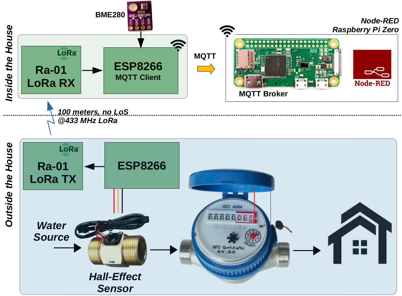 Figure 1: Block Diagram.
Hardware Modules
The following HW modules are used in this project:
- 2x ESP8266 NodeMCU
- 2x LoRa transceiver modules Ra-01
- 1x BME280
- 1x Raspberry Pi Zero W kit
- 1x Water Sensor
- Set of Prototype Veroboards
- Wires and female and male 2.54 mm headers
Arduino IDE Project Set-Up
The following libraries are required to be installed under your Arduino, or PlatformIO IDEs for it to work correctly:
- Install ESP8266 Board in Arduino IDE.
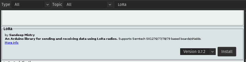
- LoRa library from sandeepmistry. Install it using the Arduino IDE Sketch > Include Library > Manage Libraries. Search for “LoRa”;
- To use MQTT with the ESP8266 we will use the Async MQTT Client Library. Unzip the .zip folder and you should get async-mqtt-client-master folder. Rename your folder from async-mqtt-client-master to async_mqtt_client. Move the async_mqtt_client folder to your Arduino IDE installation libraries folder. Finally, re-open your Arduino IDE.
- To use MQTT with the ESP8266 you also need the ESPAsync TCP library. Click here to download the library. Unzip the .zip folder and you should get ESPAsyncTCP-master folder. Rename your folder from ESPAsyncTCP-master to ESPAsyncTCP. Move the ESPAsyncTCP folder to your Arduino IDE installation libraries folder. Finally, re-open your Arduino IDE.
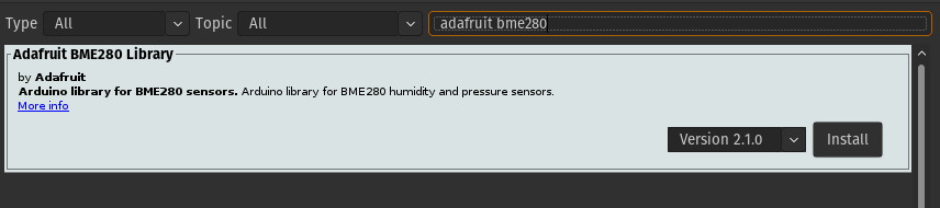
- BME 280 Adafruit library: install it using the Arduino IDE Sketch > Include Library > Manage Libraries. Search for “adafruit bme280”. Install the one from Adafruit.
MQTT Broker
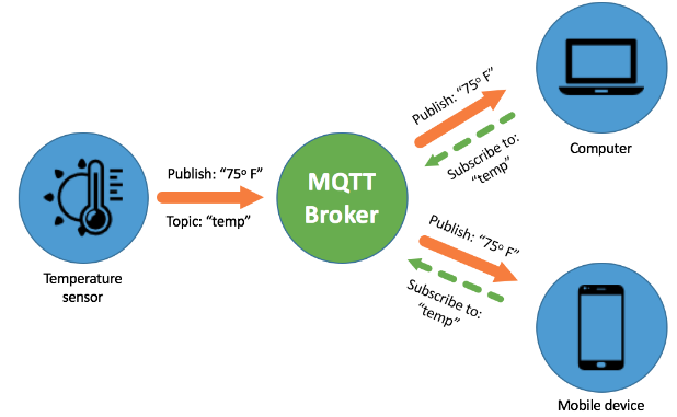
To use MQTT we will need a Broker. There are several open-source brokers available out there. I will be using mosquitto as a local instance and therefore is only accessible by its IP address and within the home network. There is also a possibility of using a cloud MQTT broker, so you will be able to access the topics outside your home network. Check how to install the Mosquitto Broker on a Raspberry Pi. If you are not familiar with the MQTT protocol, I suggest this very good article from the Random Nerd Tutorials folks.
Hall-Effect Water Sensor
To measure the amount of water that is consumed a Hall-Effect sensor is going to be used. They are worth ~13 CHF in AliExpress. This sensor requires 5V DC as power supply and it produces on the yellow line a stream of pulses where its frequency is proportional to the amount of water that is passing through it. A calibration procedure will be needed to get a representative water consumption out of it.
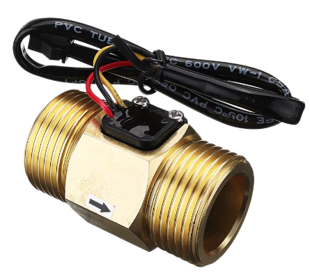 Figure 2: Hall-Effect water sensor.
LoRa Ra-01 Module
LoRa is cool and should be added to every single project, however that is not the reason why I am using it. It turns out that the home WiFi network does not reach all the way until the garage, which is where the TX module is to be installed. So to tackle down this issue, I have decided to use these sweet Ra-01 LoRa modules.
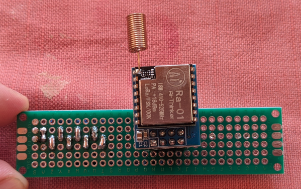
The Ra-01 ai thinker module can be used for ultra-long distance communication. This module contains basically the Semtech SX1278 LoRa chip, an SPI interface and some other discrete components on the board including an antenna. It claims it has got a bit rate programmable up to 300 kbps, however we know that to go far you must increase the spreading factor and therefore it lowers down the bit rate. Higher spreading factors are more resistant to local noise effects and will be captured more reliably at the cost of lower data rate. The operation frequency of this device is 433 MHz and the TX power is about 18 dBm with a 3V3 power supply. For this project I will be using 2 modules, one working as transmitter and the other as receiver.
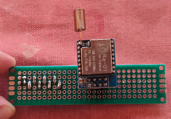 Figure 3: Ra-01 LoRa module.
Prototyping
To validate the desired behavior, I have started by wiring the modules in a prototype board. 2x sets were produced, 1 to serve as TX and the other as RX. The wiring diagram is shown is Figure 4a (TX module) and Figure 4b (RX module). The TX and RX modules code is available here.
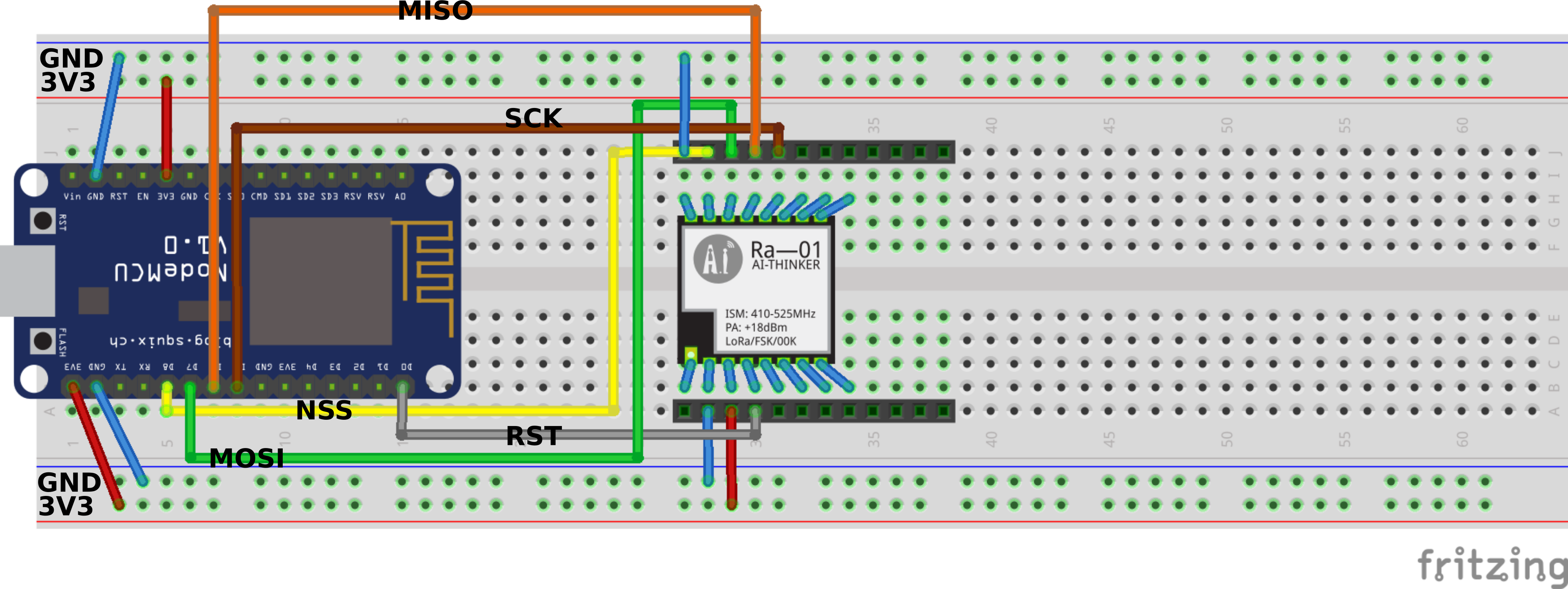 Figure 4a: Fritzing wiring diagram for the TX module.
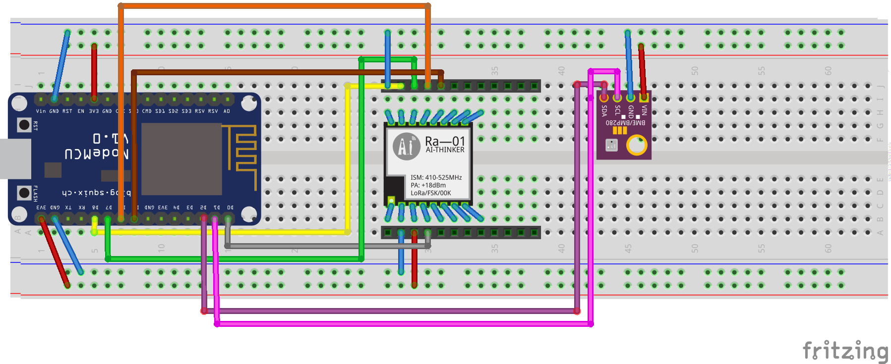 Figure 4b: Fritzing wiring diagram for the RX module.
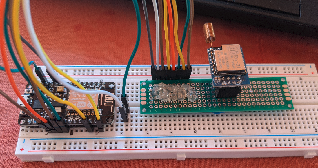 Figure 5: Prototyping...
> LoRa TX - RX
Before plugging the water sensor, I made sure that the LoRa modules were working fine. The TX LoRa module was placed in its future location (next to the water source pipes) and made it broadcast a counter value. The RX LoRa module placed inside the house, would then try to receive and parse the LoRa signal and show the LoRa payload in the serial terminal. Once verified the correct reception, went on calibrating the water sensor.
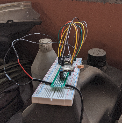 Figure 6: TX-RX testing.
> Water Sensor Calibration
To calibrate the sensor output, all that is to be done is to count the amount of pulses the sensor produces for a given amount of water that we feed into it. Of course this will give us an approximate number of pulses per liter as the water sensor is not yet connected into the real water pipe and therefore it is not under water pressure. The bellow test circuit is used for the calibration procedure.
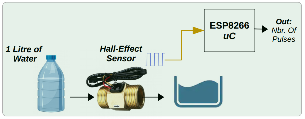 Figure 7: Water sensor calibration circuit.
The calibration procedure was not real executed as depicted in Figure 7 but the principle is the same. I had lying around a 20 liter bottle and filled it up with water within the sensor placed in series. Th water sensor output (yellow wire) was connected to an interrupt pin of the NodeMCU making a counter increment should a rising edge occur. For 20 liters of water the amount of pulses produced were 6385, making ~319 pulses per lire.
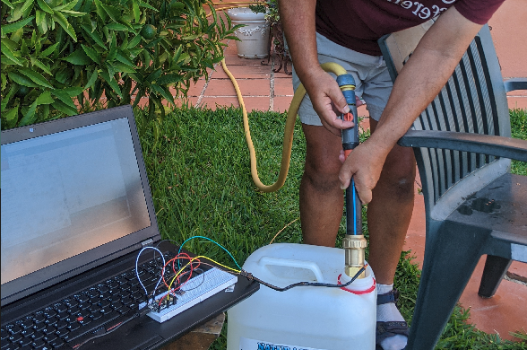 Figure 8: Water sensor calibration.
Veroboard PCB Making
Having verified the expected behavior of the prototype board, I proceeded on producing a veroboard like PCB for the whole circuit. I have started by making a socket PCB for the LoRa Ra-01 module (Figure 9). Then, using 2.54 mm female headers I produced the 2 TX and RX modules that would host the LoRa TX module + the NodeMCU module for the TX PCB and the LoRa RX module + the NodeMCU module + the BME280 breakout board for the RX PCB (Figure 10).
| Top | Bottom |
|---|---|
 |
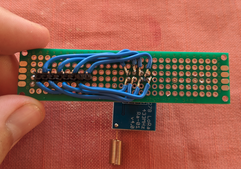 |
Figure 9: Ra-01 LoRa module PCB socket.
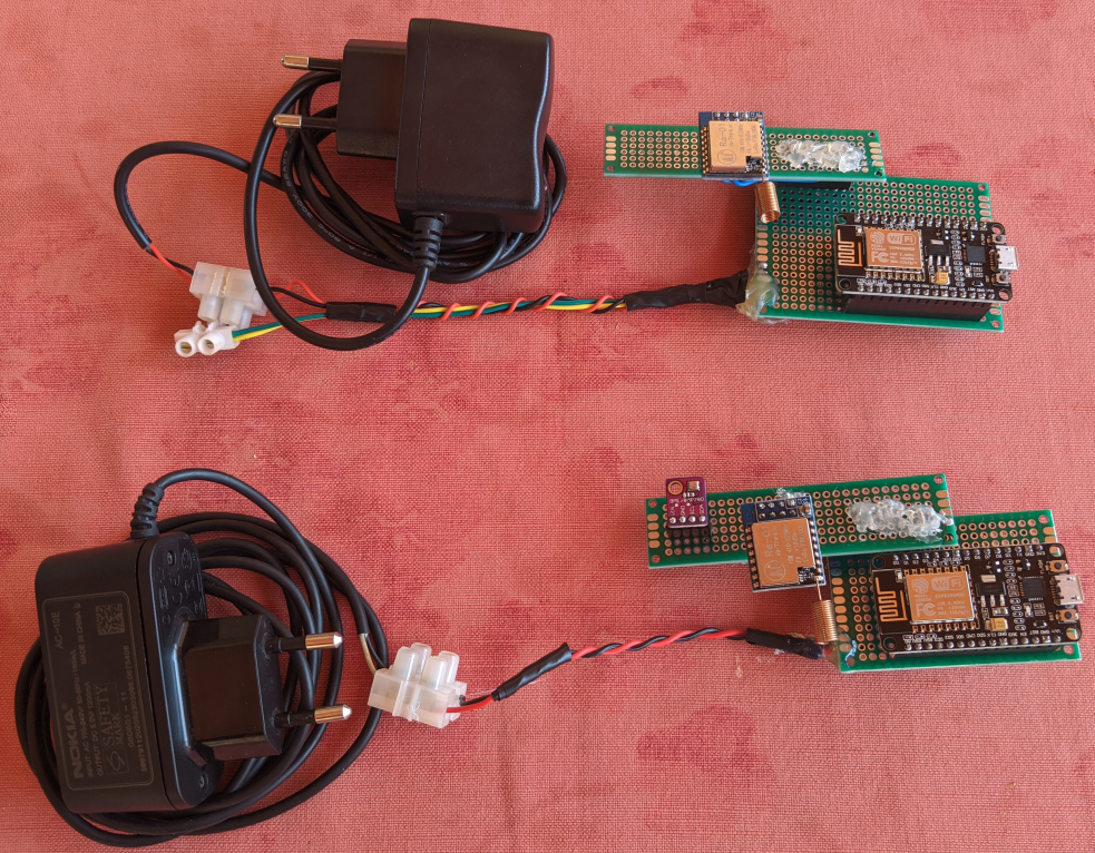 Figure 10: Final result of the TX (top) and RX (bottom) modules.
Water Sensor Installation
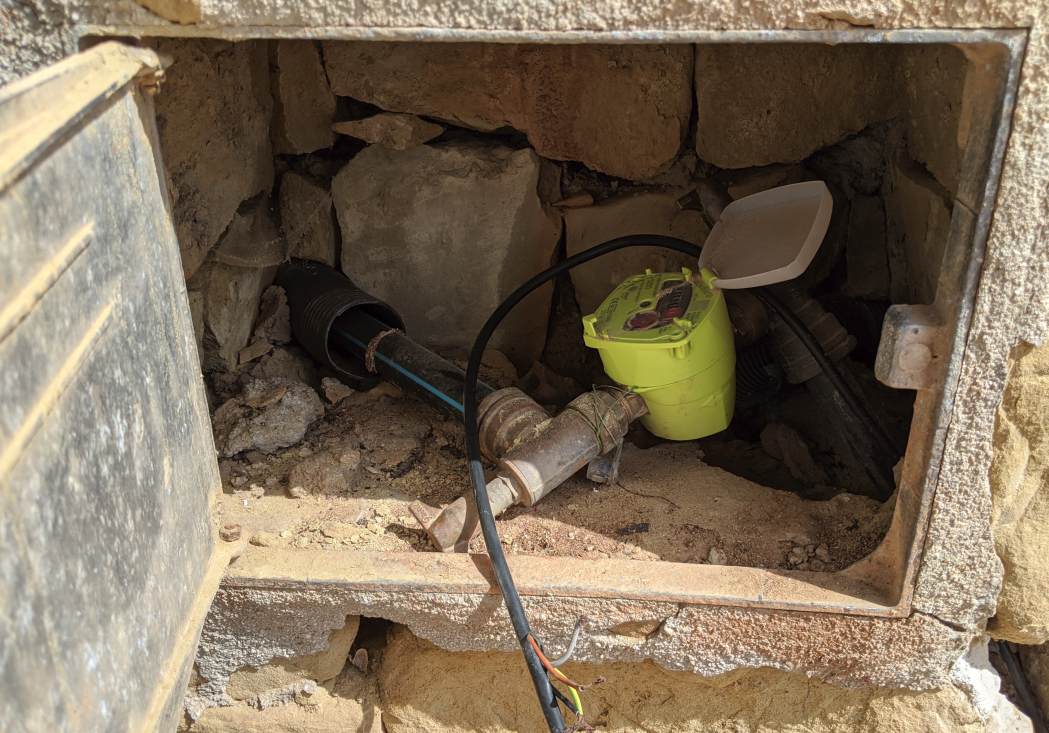
The next step would be to have real water sensor data coming in into the TX module, so we proceeded to install the water sensor in series with the water source pipe. For that, as the TX module is to be installed inside the garage, a cable was passed into the water meter enclosure (Figure 11). With all the wiring done and the water sensor installed, a simple Node-Red dashboard application was then deployed under a Raspberry Pi Zero W.
 |
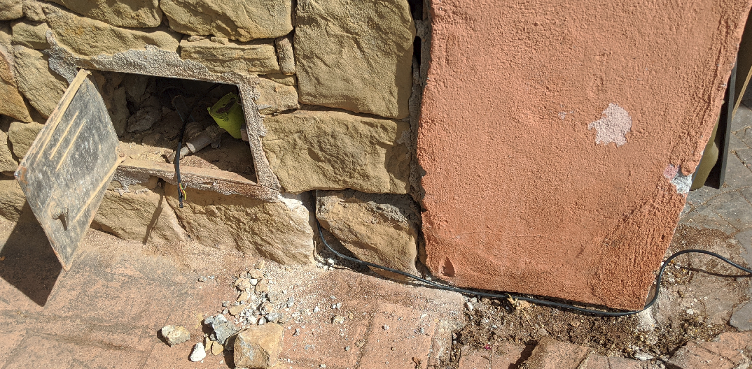 |
Figure 11: Water sensor installation.
Node-Red Front-End Dashboard Application
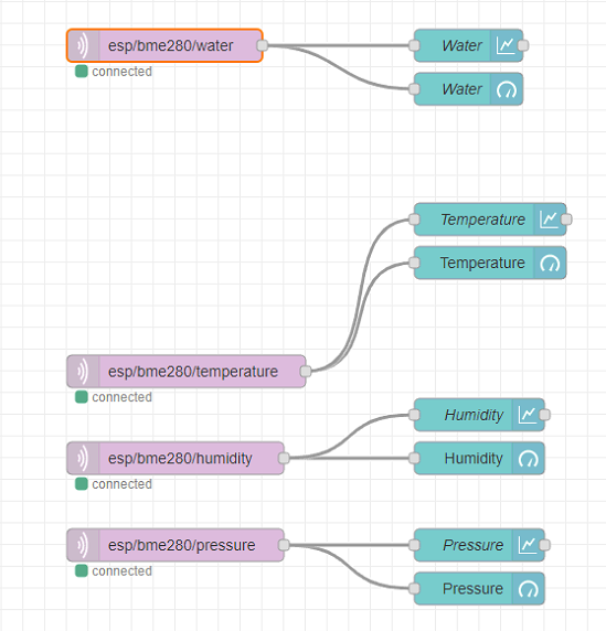
The Node-Red application is a simple dashboard with widgets and graphs. The water sensor data is transmitted by the TX module and received by the RX module using the LoRa modulation. The RX is also connected to a MQTT broker (I have used the open source Eclipse Mosquitto) running under a Raspberry Pi Zero W. The RX module gathers the data from all the sensors and publishes the converted strings to topics, esp32/temperature, esp32/humidity, esp32/pressure and esp32/water. Finally the Node-Red application uses the MQTT in nodes to capture the strings and display them in the dashboard. The Node-Red flow code is available in my GitHub project repo. Figure 12 shows the Node-Red flow and Figure 13 the final dashboard application (UI). Notice that in Figure 12 (right) is the MQTT in Node settings: localhost is the ip address of the Raspberry Pi Zero W and 1883 is the port where the MQTT broker is listening to.
 |
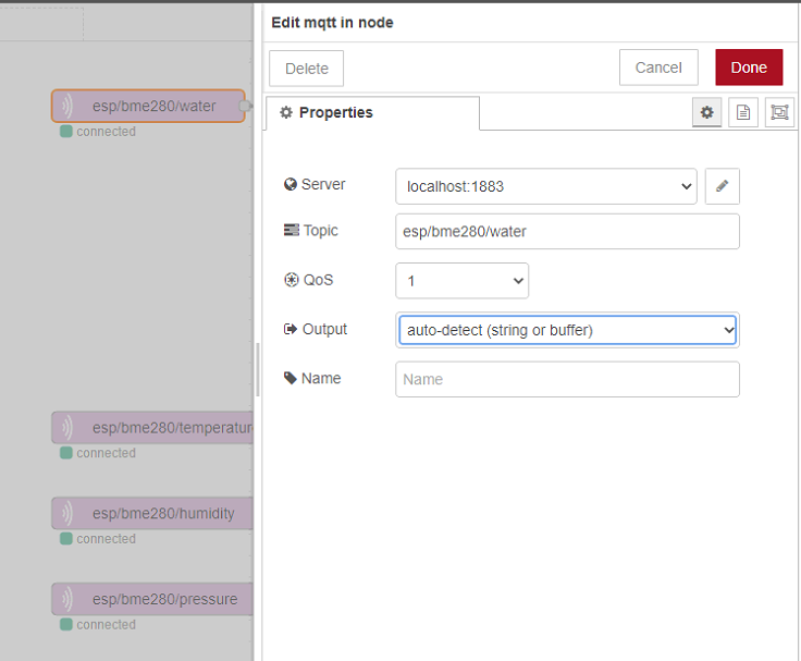 |
Figure 12: Node-Red application flow (left) and MQTT in node settings (right).
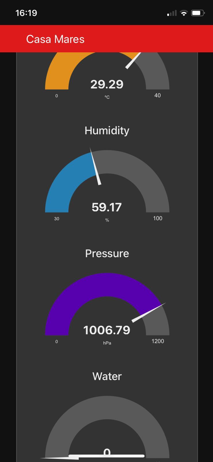 Figure 13: Node-Red dashboard application.
Wrapping Up
With this project, we have successfully installed a water sensor and displayed the amount consumed water on a Node-Red dashboard application. There is always room for improvement and here I leave some possible features and things to be done in the future:
- Have the data getting stored into a database deployed under the Node-Red environment and then be able to access old data. Currently the Node-Red data is flushed after one month of recording;
- Make a real PCB out of the 2x modules, TX and RX, and 3D print enclosures for them;
- …
- Any suggestions? :)
Comments
Leave a comment and/or suggestion on this post.